Ballast Tank, Ballast Pump, Bilge Pump, and Rear Seat
Lot's of progress!
The ballast tank is closed in. The floor is 3/8" AC plywood. The dark hole above the charcuterie table post is access to the tank. The hatch that goes over that hole is gluing up in the upper left. The front edge of the rear hatch is unsupported so I added a small oak board (eventually two boards) under it. That's what all those clamps are for. The rear floors are also installed.
I cut the slot for the ballast tank fill/drain port in the wrong place in the rear hatch and had to fill in the goof. The end result is probably a better fit than if I had cut it correctly in the first place, and the grain in the plywood patch miraculously matches almost perfectly!
Here's what it looks like with the rear hatch removed. The bilge pump and float switch are screwed to a piece of plywood that is set in an epoxy puddle. The grey hose at the top is the bilge drain hose. The blue valve and pipe below it are called a "through-hull-fitting" (homemade in this case). This is the connection between the tank and the water outside the hull. The blue valve handle is a safety feature if any of the plumbing beyond it fails.
After much pondering and changing of the mind as to how best to wire the bilge pump and ballast tank pump, I have now settled on having both be powered by a single small battery separate from the main battery. There is no real need to be able to turn the pumps on and off from the helm station.
The bilge pump is fully automatic but there is a lever on the float switch housing that allows switching on the pump if desired. The ballast tank pump switch needs to be near the flow control valves, so its power switch will probably be on the post. This layout also simplifies the helm station by removing cabling and switches from the helm panel.
Now the fun stuff
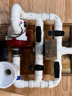
The Rube Goldberg Ballast Tank Single Pump H-Bridge Reversible Flow System is installed. For the technical/curious minded, it uses an H-bridge like what is commonly used to reverse electric motors, but in this case the H-bridge is inside out. The pump pumps water always in the same direction, but the H-bridge makes it possible to pump water in both directions to allow filling or draining the tank.

Here's how it works. In the picture below, the pipe that goes out of the picture to the right goes to the through-hull fitting. Right in the center of the picture, hidden by that center pipe, is a pipe that goes down into the tank. That big bucket-like thing with a hole in the bottom is to allow priming the system and can be ignored. The pump is in the top left of the pictures. Water goes into the pump just below the red part, and flows "up" (in the pictures and in reality) the pipe in the top left of the pictures. The water always flows through the pump from bottom to top along the left side of the pictures because the pump is a one-way pump.
When a black valve handle is aligned with a pipe, water can pass through. When the valve handle is across the pipe, water can't pass through.
Tank Filling
The bottom right valve is "open", allowing water from the port in the hull to flow into the pump. This valve handle will be painted red because it is pumping water into the boat. The valve to the left is "closed" so no water flows there. The water goes through the pump and can only go through the top left valve (also will be red) and into the tank. The top right valve is closed so no water flows there.
Tank Draining
Now it is reversed. The water can't flow from the through-hull fitting, but can flow from the tank through the bottom left valve and into the pump. The water coming out of the pump can't flow into the tank but instead now flows through the top right valve and out through the through-hull fitting.
I also started on the rear seating. It is enjoyable to finally be doing high(er) precision carpentry.
Here's what the helm station seat looks like in the boat. It is removable to reduce weight when moving the boat around on land.
The three white pine boards that make up the rear seat are held together with six Ash strips (same strips as the hull frames). I had to glue them in 3 stages.


After it was all glued I put bronze screws in from the bottom to make it even stronger.
Look closely at the grain in those white pine boards. Notice anything? The boards are quarter sawn just like that big piece of red oak I found at Home Depot! I went to a high-end lumber yard and picked through their supply to find boards that were quarter sawn.
I sat on the seat to test it. It is springy but plenty strong enough. It is really close to the rudder post. This means the tiller handle will have to be shorter. I won't do that until I've tried the boat on the water to get an idea how long is comfortable.


Comments
Post a Comment